3D Printing with .xyz Data
Introduction:
This document will go over the main steps needed to turn a point-cloud .xyz file of a real-world surface into a 3D-printable .stl file. The programs I used were MeshLab and Solidworks. MeshLab is free and open-source, while Solidworks is not. However, most of the steps taken in Solidworks should be easily replicated in other CAD programs. Free MeshLab Download
Process Overview:
In MeshLab:
- Import .xyz file
- Reduce size of file (amount of vertices)
- Re-orient vertices
- Create mesh
- Edit mesh
- Move origin
- Export as .stl
In Solidworks:
- Import .stl file
- Create mesh body
- Create base
- Trim edges
- Export as .stl
You can then open this .stl in any slicing program and print!
In MeshLab:
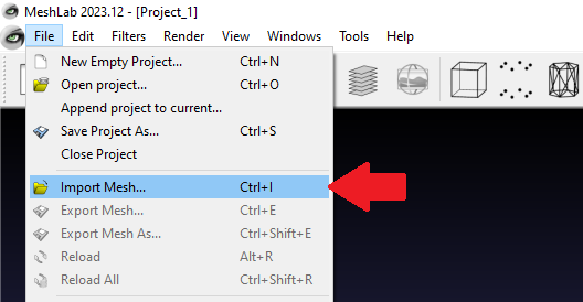
1. Import .xyz file
Files > Import Mesh
2. Reducing file size
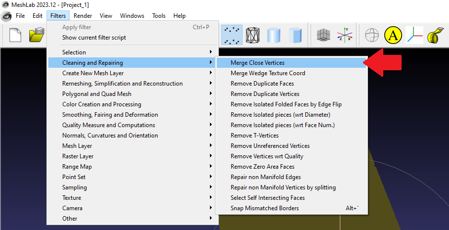
This step will use a function in MeshLab that merges vertices within a set distance of eachother to reduce the total amount of vertices.
Filters > Cleaning and Repairing > Merge Close Vertices
This will open a menu:
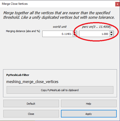
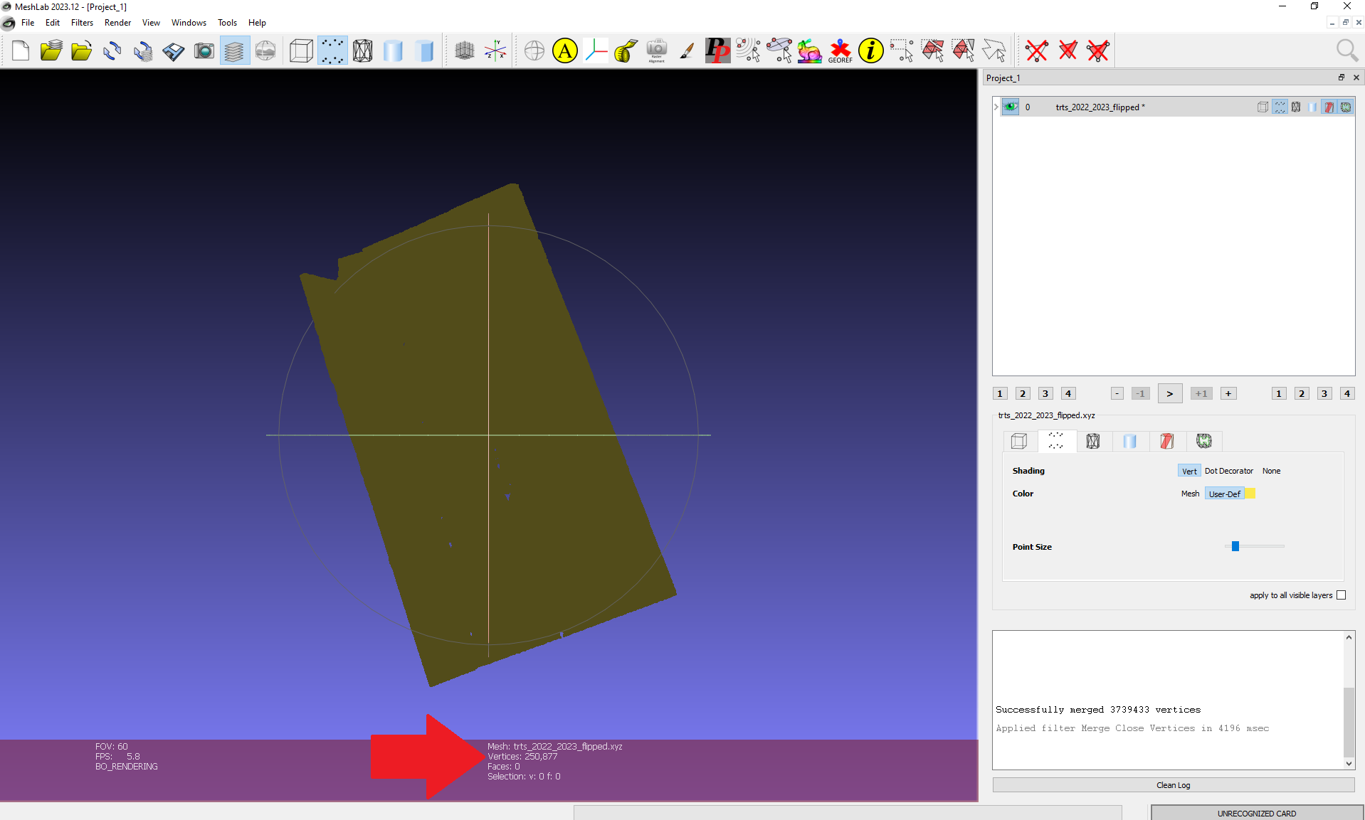
Starting with a file size of about 4,000,000 vertices, setting the “perc on” value to 10 reduced the file to about 250,000 vertices. This was just about as much as Solidworks could handle for me later on, but it might be different for you. Try a value for “perc on” and hit apply to see results. The number of vertices in the file are displayed on the bottom of your screen (shown below). Close the menu when finished.
3: Re-orient vertices
Now we will rotate our points to better match the x, y, and z axis. This will make it easier to create a square end product.
Filters > Normals, Curvatures and Orientation > Transform: Rotate
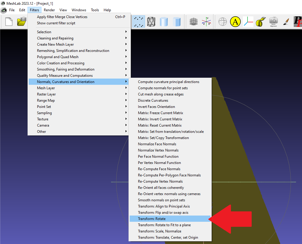
This will open a menu:
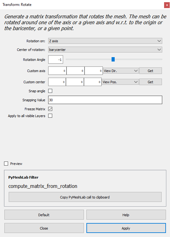
Select the rotation axis, make sure to select “barycenter” as the “Center of rotation”, and change the rotation angle. Start with a small value. Hit apply to rotate the vertices. Each time you hit apply, the vertices will rotate according to the specified rotation angle. This lets you fine-tune their orientation. Close the menu when satisfied with your orientation.
4: Create mesh
In this step we will create a mesh from our vertices. First we have to compute normals for point sets.
Filters > Normals, Curvatures and Orientation > Compute normals for point sets
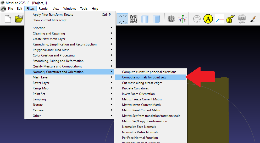
This will open a menu:
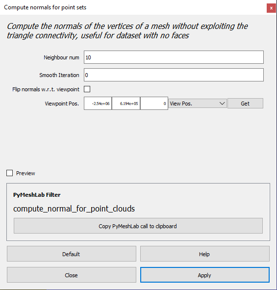
The default settings work. Hit apply and close the menu. Next we will create the actual mesh.
Filters > Remeshing, Simplification and Reconstruction > Surface Reconstruction: Screened Poisson
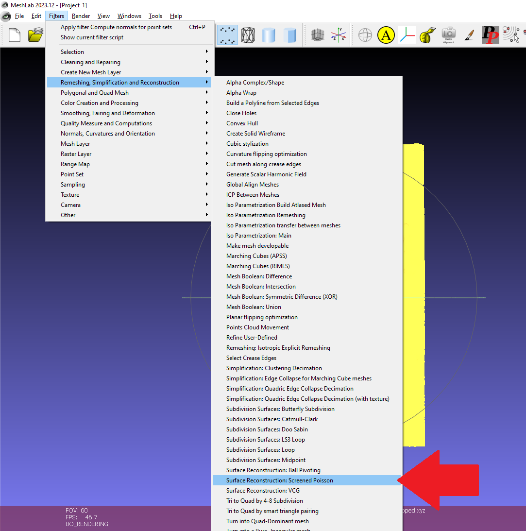
This will open a menu:
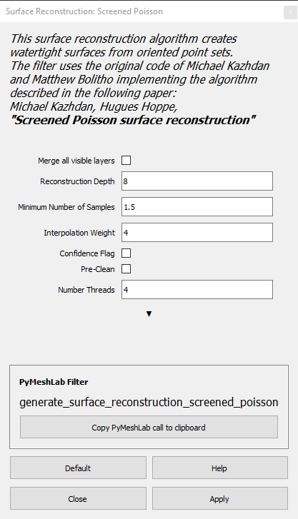
The default settings work. Hit apply and close the menu. This will create a new mesh layer in gray (shown below). The original vertices are highlighted yellow.
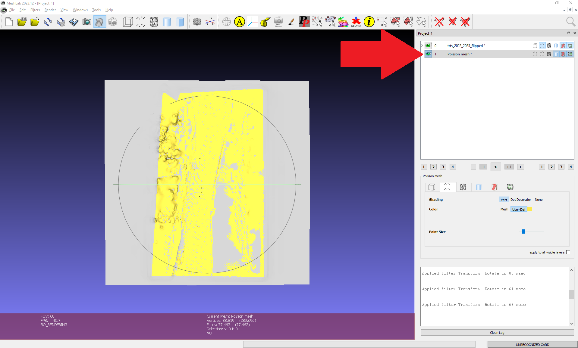
5: Edit mesh
You’ll notice that the new mesh is larger than needed. In this step we will trim it down to fit our actual data points. Click the button indicated below. Hover over it with the mouse and it should display “Select Faces in a rectangular region”.

The following red info box will pop up on the upper left part of your screen:
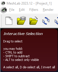
Click and drag with the mouse to highlight your desired region of the mesh, then use the “I” (invert all) key to select everything outside your desired region. Anything you would like to remove should be highlighted red. Now select the “Select Faces in a rectangular region” button again and the red info box should disappear. Then click the last button on the top taskbar (shown below) to delete all selected vertices and faces.

Then, we will repair all non-manifold edges. These can cause issues later in the process when importing a final 3D object into slicing programs.
Filters > Cleaning and Repairing > Repair non Manifold Edges
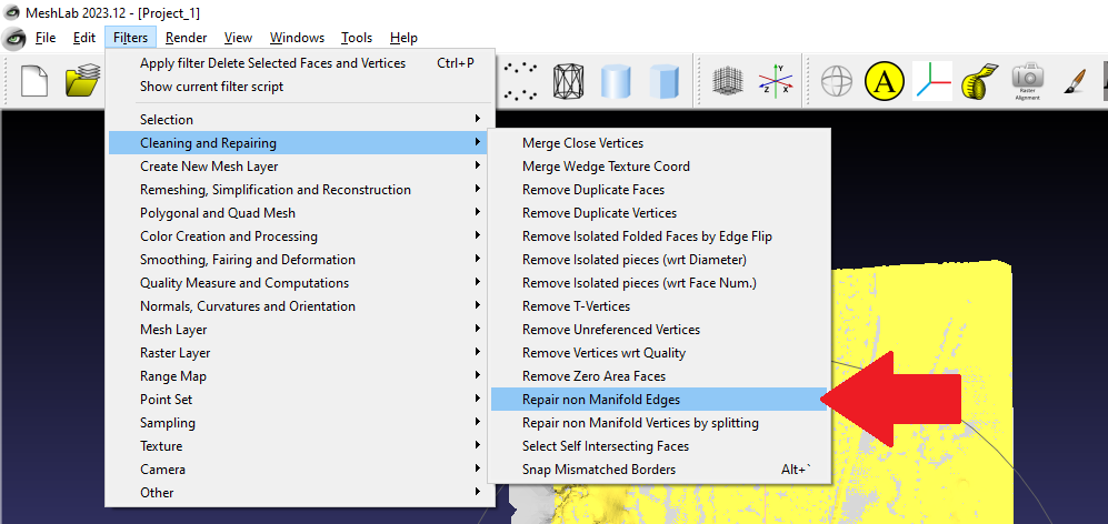
This will open a menu:
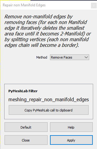
The default “Remove Faces” option works. Hit apply and close the menu.
6: Move origin
Because my original data was in UTM coordinates, the actual origin of the mesh (0, 0, 0) was super far away. This causes issues when importing the mesh into any CAD software. As soon as I’d try to even rotate the mesh, it would fly off into the distance. To solve this problem, we will move the origin of the mesh to its centroid.
Filters > Normals, Curvatures and Orientation > Transform: Translate, Center, set Origin
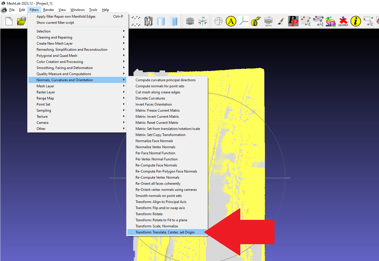
This will open a menu:
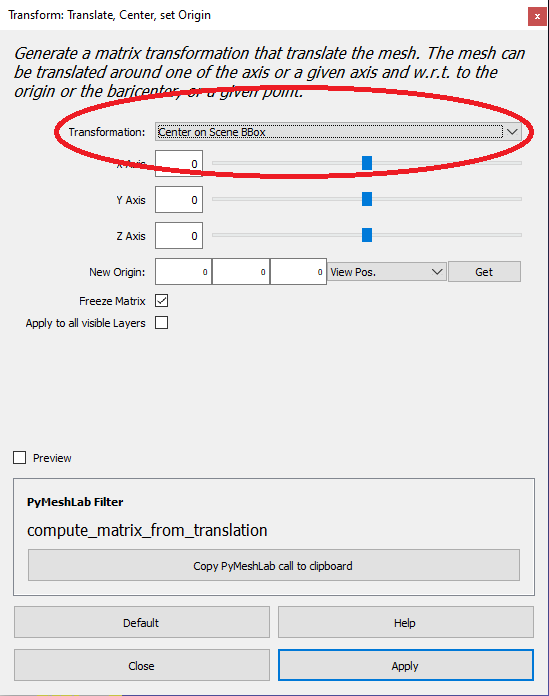
Click the drop-down arrow and change the “transformation” option to “Center on Scene BBox”. Then hit apply and close the menu. Your mesh might disappear! Don’t worry, it is still there.
7: Export as .stl
First, make sure the “Poisson mesh” layer is highlighted on the right upper part of your screen.
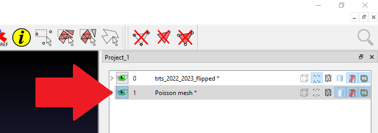
Now we can export our mesh as an .stl file.
File > Export Mesh As
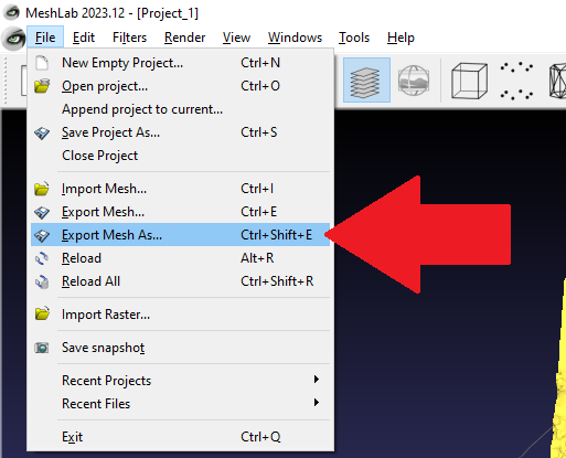
In Solidworks:
1: Import .stl file
Open your mesh .stl in Solidworks.

Notice that it is imported as a “graphic” in your solidworks feature tree.
2: Create mesh body
Now we will turn this “graphic” into a mesh body.
Mesh Modeling > Convert to Mesh Body
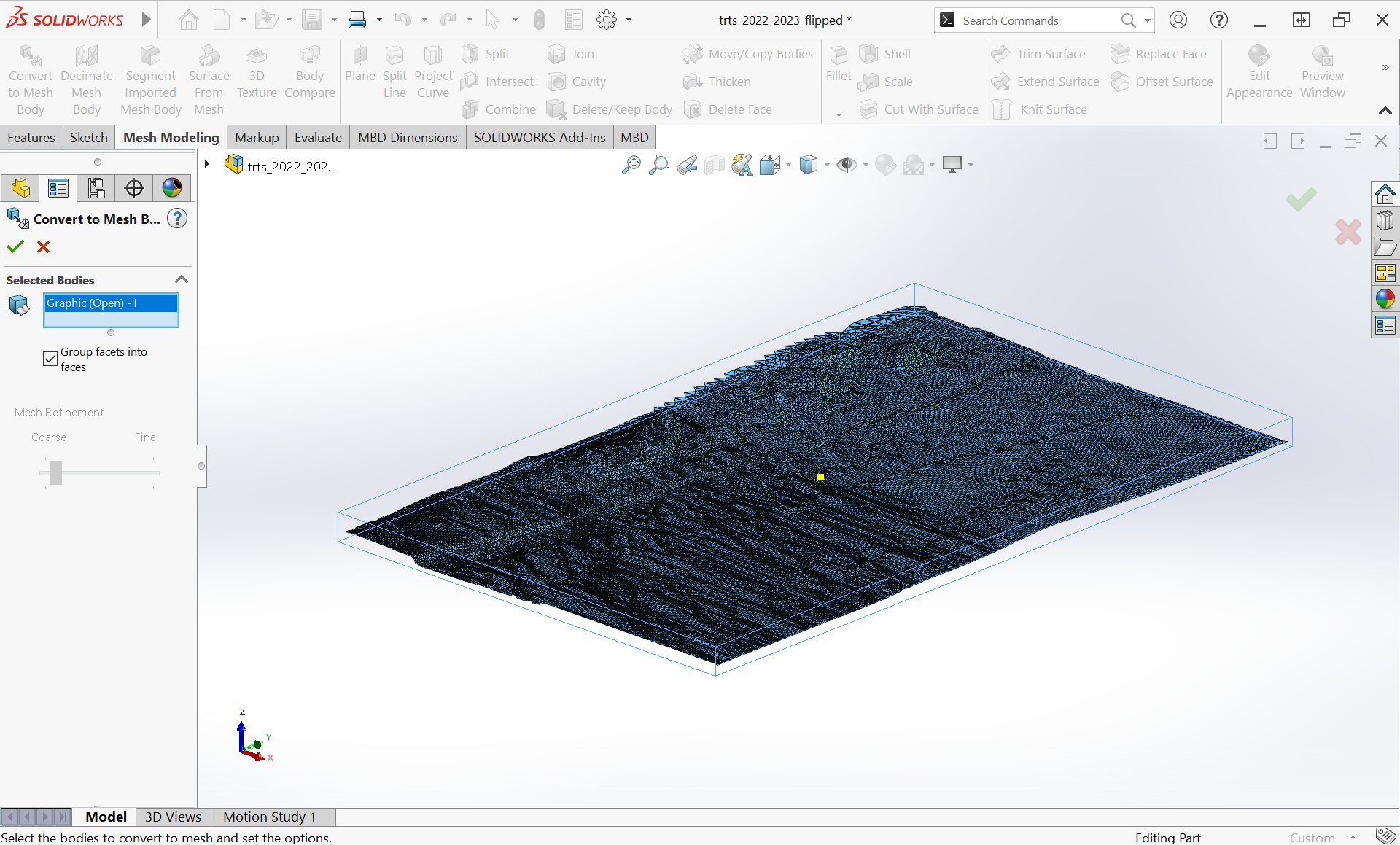
Click on the “graphic” to select it. Then hit the green check. Now a “surface” should appear in your feature tree.
3: Create base
Now that we have a surface, let’s create a base for our object. We will start by creating a new plane.
Features > Reference Geometry > Plane
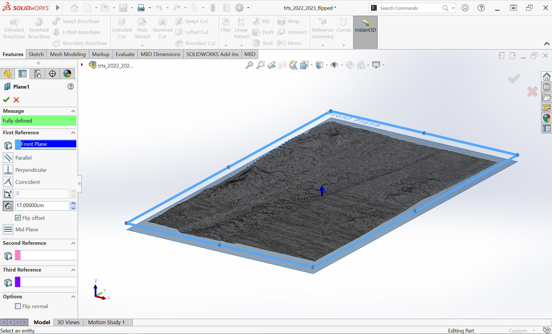
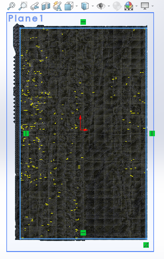
Select a plane parallel to your surface as a reference, and offset the new plane so that it does not intersect with your surface. Now create a sketch on your new plane that will form the outline of your 3D model. Make sure that no part of the sketch reaches over the edge of your surface. An example is shown below with the rectangular sketch highlighted light blue.
Next we will extrude this sketch.
Features > Extruded Boss/Base
Select “Up To Surface” in the menu shown below and select your surface as the reference geometry.
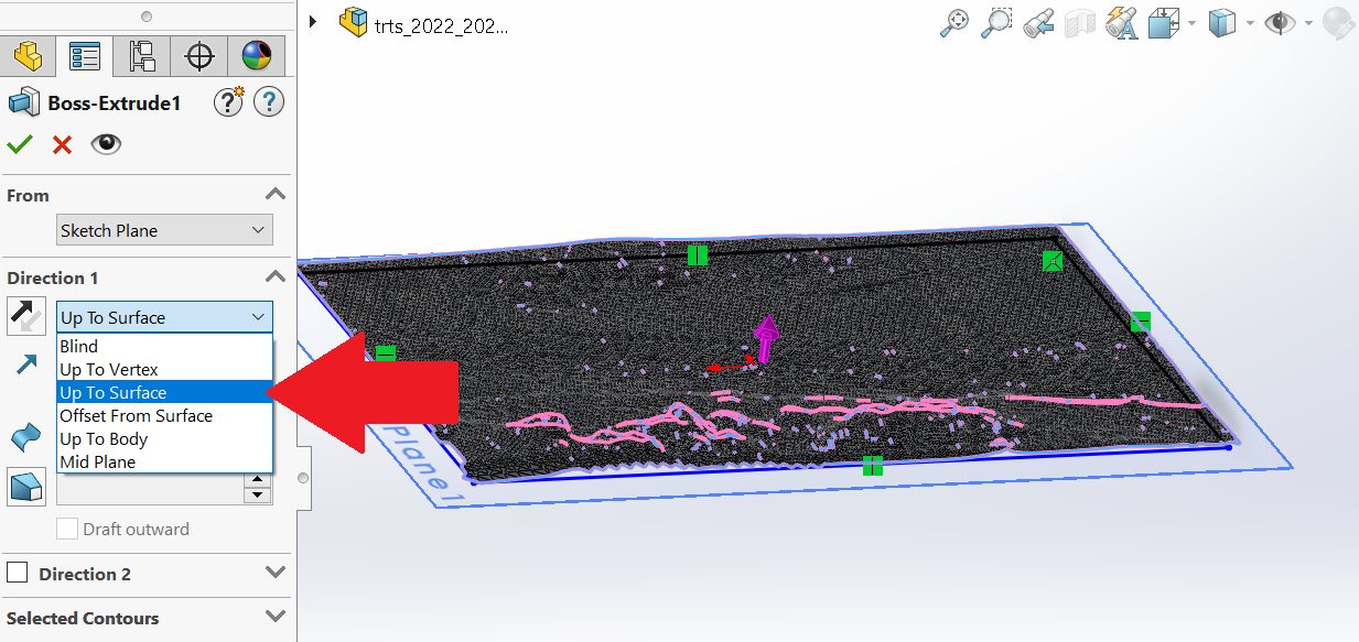
Hit the green check to extrude.
4: Trim edges
Now we will trim the overhanging edges of the surface from our model.
Mesh Modeling > Trim Surface
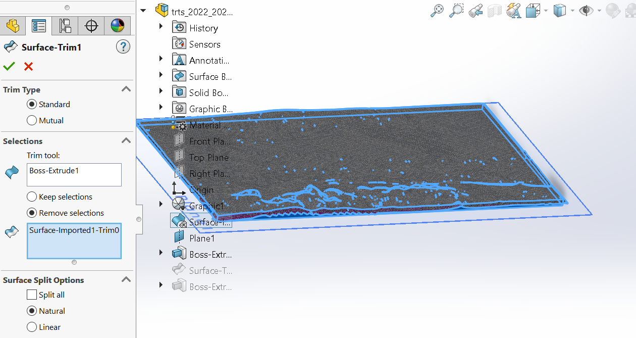
Select your extrusion as the “Trim tool” and your surface as the surface to trim.
5: Export as .stl
Now save your part as an .stl and export to any slicing program to print.